Welcome to Kittenbot Team’s Documents
Category:
Kittenbot Robotic Kit
Here is the tutorial for kittenbot basic metal chassis robotic kit
Introduction and mechanical assembly instructions
Kittenbot Introduction

Thank you so much for choosing kittenbot robotics. The following series of tutorials will lead and open the door to graphical programming.
Kittenbot Robotic kit is the first production of Kittenbot Team. It has a sheet metal body, with the finely crafted process, make it stable and good looking. At the same time, there are many compatible holes in the sheet metal car, which can be easily combined with the LEGO blocks.
In addition to being a DIY remote control car, you can also turn it into a drawing robot and draw different patterns according to your instructions. With our expansion kit, you can also upgrade to tank cars, casters, omniwheels, and more.
We have also developed a Scratch3 based graphical programming software to coop with this kit, names Kittenblock.
For children, we wish kids to focus more on graphical programming without worrying about the grammar of code programming and improving children’s programming confidence. It can also quickly improve the level of programming education and establish programming education for schools or training. The core concept of Kittenblock if to focus more on logical thinking and problem solving than on tedious programming processing.
For teachers, the Kittenbot robot not only cultivates students’ hands-on skills but also enhances students’ programming thinking and ability to solve actual problems. With kittenbot’s kits, you may quickly improve the level of programming education and establish programming education for schools or training. We will provide detailed tutorials on upcoming serials robotic kits. Actually, we have tested our product and software in real teaching scene over China, HongKong and Taiwan, and confident to push it to global.
For makers, Kittenbot robot is your stepping stone to open the programming robot door. Kittenbot uses an Arduino Uno compatible mainboard. If you find it difficult to get started with arduino, or if you want to master electronic programming techniques, you may wish to start with the Kittenbot robot. Beyond an entry level tutorial kit, kittenbot is also suitable to make all kinds of DIY projects.
What is included in kittenbot robotic kit
- DC Motor
- 9 Gram Mini Servo
- 28BYJ Stepper motor
- LED lights Module
- Cat Ear Ultrasonic Sensor with RGB lights
- Buzzer Module
- Button Module
- Inf RGB Ring Module
- WIFI Module, etc
Assembly

There is a detailed instruction shipped with this kit. We believe you may find no difficult on assembling.
Here again some note on mistakes you may take.
Because the series of tutorials are based on the following connection or wiring, we hope you follow these connections, or you may find the robot won’t act as expected.
Error-prone
- Left and right motor socket, the left side is inserted on the left, the right side is inserted on the right (as pictured)
- The red and black lines of the motor cable should pay attention to the order of insertion (red and black on the right)
- Servo 3PIN Installation Order (Pin Order)
- 4PIN ultrasonic adapter board mounting sequence (pin order)
After Finish
No difficulty, just patient and check it carefully.

On the following tutorials, we will open the door to the graphical programming of Kittenbot robot.
FAQ:
Accidentally smoke the mainboard with wrong wiring?
Normally no, wrong wiring will just prevent the modules to work the right way. But we still encourage you to check the wiring as pictured before powering on.
What if I still have a lot of modules left after assembly?
Kittenbot robots can be equipped with some common electronic modules in addition to the assembly of a car. We will show in the upcoming tutorials.
Why my robot don’t move after powering on?
Kittenbot is not an electric toy car, its main function is to learn to programme. So you need programming to make it do something.
Where is the power switch on the Kittenbot?
The mainboard of kittenbot is named RosBot, there is no power switch. All you need to do is just unplug the power plug.
What is the voltage input of Kittenbot?
The power socket accepts 5~12V input. You may also power the robot from USB with a portable power source.
The kit comes with a battery box that holds six AA batteries, should be enough for play around. For the sake of shipping restrict overseas we can’t give you a more powerful power source, sorry for that. We still hope you can get it a more powerful equipment upgrade.
Will the robot damaged with both USB and external power plugged in?
No, we have internal power source checking circuit.
Can I unplug the jumper near the USB port?
No, every jump cap on the circuit board has its role. Make sure you know what you are doing before removing any of it.
What is the use of that WIFI module?
It gives you access to control the robot wirelessly, we have provided an App may sync your scratch3 programme to run on a mobile phone. We will show you in the advanced tutorials, for now, use USB cable only.
What is the function of the button next to USB port?
The mainboard’s reset button. If you want to re-execute the program or restart the car, you can press the reset button.
Can I make it a line follow patrol robot?
Kittenbot robots support extensions. We provide a five-way black line inspection module. If you want it, you need to purchase them separately.
What is the difference between the Rosbot and Arduino?
In fact, their cores are the same. It can be understood that Rosbot is an upgraded version of Arduino. Because Rosbot has integrated some of the motor’s driver chips, and wifi Bluetooth expansion, interface, I2C interface and so on.
Can I use Arduino IDE?
Yes, if you use the Arduino IDE for programming, please choose UNO in the board list. You may also need to copy the arduino libraries under the kittenblock install folder to your arduino IDE.
For beginners, we advise you to try to translate graphical blocks to c++ code in Kittenblock.
Is there a document for Arduino control instructions?
For now, Kittenbot robots are primarily targeted at primary and secondary school students and enthusiasts who do not understand electronics. We may finish this part later.
Install Kittenblock
The Kittenblock Graphical programming software
All Kittenbot products can be programmed via Kittenblock. Kittenblock is developed over the latest MIT scratch3.0 codebase and focus on hardware interacting. Kittenblock is designed for primary and secondary school programming education and personal enthusiasts DIY projects. We break the barrier between software and hardware by graphical programming.
Features: low entry level, Get started quickly and understand it easily.
The following picture shows the interface of Kittenblock. Kittenblock is based on Scratch3.0, the UI is visually very different from the Scratch2.0. The UI is brighter, more vibrant, and more consistent with the tone of young people learning. It is a graphical software that has a good experience in the market and supports the most electronic devices.

Kittenblock is maintained by KittenBot Team. We are committed to building the best graphical programming software in China. Explore the connections of hardware and software. Let’s enjoy DIY and pay more attention to the creative work and innovations.
Software Download
Basically, Kittenblock update every 1~2 weeks, due to frequent updates, there may be small bugs in different situations. Feedback and bug report are welcome, we will fix the bug as soon as possible.
Download Link (Latest 1.72)
The installation process is simple, next step on each prompt. If your anti-virus firewall shoots a warning please bypass it and let us know. We will contact the anti-virus company for a false alarm. Please make sure you have downloaded the correct software according to your operating system.
If you encounter any problems during the installation process, you can post in our forum. We have colleagues who are responsible for the technical maintenance forums and will respond to them as soon as they see it.
Driver Install
If your os is windows you may need to install USB-Serial drive to communicate with the mainboard. After kittenblock installed, click the gear icon on the top right header panel. Click install driver in the pop-up windows.

For win10 you may need admin privilege to start the driver install programme. Go to kittenblock install spot and inside the drivers\ch340win folder, you may find the driver install programme. Right-click and execute it with admin privilege.
Quick start of Kittenblock
Here are the main steps to get start of your robot kit.
Select Kittenbot in the up-left drop down

Plug in the USB cable to rosbot mainboard, then select the right serial communication port
If you can’t find the communication port please check if the driver installed correctly.

Click the chip icon next to example to restore firmware

It may take 10~20 seconds to finish the restoring process.

Now you are good to go
Second way to restore firmware
Switch to code panel

Click the Restore button then the Upload button

You may also check the source code of firmware here.
Summary
Successfully go through the steps above has proven that you have successfully started the Kittenblock graphical programming software, next tutorial will start the actual programming.
When you are familiar with all the functions of the car, you can program it at your own pace.
Then summarize the steps:
- Plug in the USB cable
- Select robot type in the software, serial communication port
- Restore firmware
If you encounter any problems with the above steps, please feel free to leave a message in our community http://kittenbot.cc/bbs/ or email us info@kittenbot.cc
Motor Move
The motor mounted on metal chassis

Graphical blocks for kittenbot

The first group of blocks for motor controlling. And we will only use these guys in this tutorial.
Functional description of the blocks
You may find the M1A~M2B definition on rosbot mainboard
single motor execute

dual motor execute


To test the block
- Drag your desired function to workspace.
- Set a speed and a motor slot
- Then click the block.
- Check how the motor runs responding to the blocks you clicked.
Make sure you have restored the firmware and opend the communication port.
The difference between online mode and offline mode
Online mode:
You have both kittenblock and serial com port opened. Actually, kittenblock send commands to default firmware to execute peripheral functions.
Offline mode:
When you are confident that the programme works, try to translate into arduino c++ code and download to the mainboard.
The internal arduino build of kittenblock will translate the c++ code to a hex firmware and overwrite the default firmware. Every power recycles or reset will make the programme to start over again.
The offline mode you don’t need kittenblock communicating to mainboard, neither you can click a block and make it run.
The motor example
Try to load the motor example from top menubar Example button

Find the motor move example

Click to load the example, and click the green flag to see how it works.

Then switch to the coding panel and translate all the blocks to c++ code

Upload your code to the mainboard. Then unplug the USB cable and use an external power source to check if the robot works as the online mode.
PS: You need Green Flag to start a run process or a c++ code translate entry.
Debugs
If you find your robot won’t work, please check the list below:
- Is the robot type selected correctly?
- Is it connected to the COM port?
- Is the USB cable connected?
- Are the blocks correct? Missing green flag blocks?
ServoSweep
Servo Mount

Blocks for servos

Here is the servo block, the first slot indicates which pin you plug you servo in. The 2nd slot is the degree to move to. The last slot is the speed, 255 means to turn to destination degree instantly.
Sweep Servo online
Make sure you have restored the firmware before using online mode
Drag the block to the workspace area, you can set the angle range from 0-180. It is generally recommended not to use the limit value, it may tremble due to the individual differences of the servo.
Try to set a small speed value to see how the servo moves to target degree. Then a large speed.
Now, let’s make a servo sweep programme as pictured below

Click the green flag above the stage

Or just click the green flag block

Seee… The servo sweeps ~ :p
Now try to modify the speed of each servo block.
Be noticed that we need manually insert a delay block between each sweep as the block run asynchronously.
Make the robot’s head sweeping:
Just translate the graphical block to c++ code as we narrate in the last tutorial.
You can also join the motor movement command with the servo turning blocks together. By make it sweeping while running around.

Debug
Again the checking list if you find your robot won’t work.
- Is the robot type selected correctly?
- Is it connected to the COM port?
- Is the USB cable connected?
- Are the blocks correct? Missing green flag blocks?
Nekomimi RGB pixel
The Nekomimi Module
There is a very cute ultrasonic module shipped with kittenbot basic kit. We give it a cute name too, ‘NekoMimi’ which means cat’s ears.

Wiring
To make the ultrasonic module sweep with the servo, we need an adapter board. And plug the nekomimi module onto the adapter board.

Adapter->Mainboard
- V —— 5V
- 1 —— D2
- G —— GND
- 2 —— D3
Double check the wiring before you power on.
In this tutorial, we only show how to control the RGB pixel to the ears.
Blocks description
There are four blocks in kittenblock to control RGB neopixels, which may compatible with any ws2812 based module or strips.

You may figure the function by the name, here we go detailed into the basic pixel setting block.

The functional slots from left to right are:
- which pin used to control the RGB pixel
- which pixel you want to manipulate
- the color panel
Play the RGB pixel in online mode
Make sure you have restored the firmware before using online mode
Drag in couple RGB blocks, make sure you set the PIN to 3 on each block.

Click on each block to see if the RGB pixel works.
Be noticed that we have only two pix on our module, any pixel index setting over 2 won’t work. If you have an RGB strip you may connect it to the mainboard and take a try.
RGB pixel looping
Drag a graphical code as shown below, you may also find it in the example panel.

Click the green flag to see if it works.

Next, translate the blocks to c++ and solidify to the mainboard.

Nekomimi Ultrasonic Sensor
The Ultrasonic Sensor

Wiring
The wiring is the same as last post, and double check the wiring before you power on.

Adapter->Mainboard
- V——5V
- 1——D2 // The Ultrasonic Sensor
- G——GND
- 2——D3 // The RGB pixel
Block for distance sensing

There is only one input slot in the block, which PIN you connect to.
The detecting distance ranging from 5~200cm.
Read distance
Make sure you have restored the firmware before using online mode
Drag a distance block to the workspace and click, you will read the distance echo.

If you read 999 please check your wiring.
Shake head if the robot detects someone

According to the above figure, drag the blocks out of flyout panel to make a complete program.
The green flag block is necessary.
The robot will shake head if your palm is too near.

PS: If you have ever used other ultrasonic sensor like sr-04, it needs one of each trig and echo pin. Kittenblock support almost most common arduino compatible electronic modules, you may find Arduino in the hardware dropdown.
PS2: If you have a 2.0 version of NekoMimi module it will extend to 300cm and support input voltage of 3.3V.
Buzzer
Wiring of buzzer module


The wiring is simple, just be noticing that rosbot mainboard has a series of 3pin extensions:
- Red pins: 5V power output
- Black pin: Ground
- Yellow pin: Signal
Blocks for the buzzer

This block is to control the buzzer tone.
The first slot is which pin you are connecting to a buzzer. The other two slots indicate frequency and time duration.
You may test the buzzer module by hitting the block.
You may also check out the buzzer example to ‘Beep, beep’ in a different frequency.

And upload to the mainboard

Siren effect
We may also make a police siren effect by doing some math and coding.

Sorry for that we can’t show the sound effect on markdown, you have to test with your ears.
Buttons


Blocks for the button

The button is of shape sharp corner, which means it will only return 1 or 0(true or false). 1 if you press the button, 0 if release.
Please note that the button module is actually pull up, means it will return 0 if you read the raw pin level while pressing. We have inverted the return value internally.
Read the button on the fly
Make sure you have restored the firmware before using online mode
Click the block and get the status report.

Handling an Event
The button only executes once every time you execute it, no matter online or offline mode. So we need an infinite loop to continuously checking its status.
The demo code in our example is almost the same as the ultrasonic demo, the only difference is that we use a different trigger source.

By clicking the green flag to execute the code block.
Translate to c++ and download


You can also start the motor the same way if you don’t want the robot to start running right after reset.
The infi RGB ring
The infi RGB Ring Module
The infi RGB ring may also plug into the adapter board.
Here we use the same wiring scheme as the ultrasonic module.
Adapter-Mainboard
- V —— 5V
- 1 —— D2
- G —— GND
- 2 —— D3
The pixel arrangement is shown in the pic below

Blocks for RGB pixels
Here we have more than two pixels and more freedom of coding. The blocks for RGB are the same as chapter 5.
Testing the RGB module
We make a simple blinking testing programme to loop between RGB colors. Please note that a Black actually means turn the RGB off.

Make sure you have restored the firmware before using online mode
Then we translate it to arduino code and download.

The final effect

The chapter 7 to 9 could be kind of tedious but may get you familiar to kittenblock and the wiring process.
Drawing robot
Assembly
To transform your robot into a drawing robot, you may need to remove the DC motors. And rewiring everything as shown in the pictures.
Each motor should connect to the correct motor socket.

Big Notice: make sure the stepper motor’s red wire connecting to VIN.

Use the nylon tie to fix the battery holder to the chassis.

Block for steppers
There are many stepper support blocks in kittenblock. You may precisely move your robot, turn in precisely degree or even draw an arc.

The Pulse Per Meter block is to calibrate the linear moving. The theoretical value is calculated by checking how many pulses we need send to steppers to drive 1 meter. You may fine-tune this value if you find the robot not moving precisely.
The Wheel Base block indicate the distance of wheels, this is also a theoretical value, not the distance you actually measure the wheelbase distance. This is used when calculating the turning degree and arc moving, you may find a clue in the kittenbot firmware source code.
Drive in online mode
Move forward and backward
Make sure you have restored the firmware before using online mode

Hit the block group and check if the robot move 20cm forward and back. Make sure you are still using USB cable connection, for now, we will show how to use wifi module to do the online mode functions later.
Draw a Star
You may draw a five-angle star by turning 135 degrees around on each turn, that is the inner degree of a five-angle star.
Drag the code block as shown below, and burn it to the mainboard.

The robot may wait for 3s before start, with the LED 13 blinking.
Try turning the 135 degrees if you find the shape won’t close very well. As there is a band of error in the real world.
The finally moving

Wifi Module
Why put the wireless connection tutorial here is that we have found may users try to use the wifi module the first time got the kit, before they can wiring correctly or drag a working code.
It could be a mass if you can’t find a clue which parts go wrong, most of the time it is not the communication go fails but the origin wiring or coding is not correct.
If you got here we are confident you have already mastered the core of graphical coding and hardware wiring. Check if your robot works with a USB cable connection before putting it on air.
The working modes of wifi module
There is two working mode of wifi module.
- AP mode, the status blue led will be always on, and blink every 3 seconds.
- Station mode, the status blue led will be always off, and blink every 3 seconds.

AP Mode
AP mode means the wifi module act as an accessing point and you may find AP node starts with ESP_XXXXXX and without password in default.

Station Mode
Station mode means that the module has joined your home/workspace router, you may find your wifi module in Kittenblock if successfully make it join your local network.

We always recommend using wifi module in station mode, as it is more stable and may access to even more advanced functions like App, IoT, roaming etc.
Join wifi module to your local network
There is two method to join the wifi module to your LAN, the first one to use the web page to config.
Join LAN with the web page
Connect wifi module’s access point with any device with a browser, like your laptop or mobile phone. In the browser type http://192.168.4.1 you may find the config page below.

Navi to Wifi Station page by clicking the corresponding button on the left panel.
You may find a list of access points near around.

If you can’t find the searching list, please switch to STA or AP+STA mode.

Check your router’s tag and enter the password then click connect.

Wait a while, if everything goes fine you may find your device disconnected from the wifi module. And the LED of wifi module became off and blick every 3 seconds.
Now open kittenblock and you may find the wifi module in your LAN.

Most thing you do with a USB cable will work with a wifi connection.
Join LAN with our app
You may also let the wifi module join your LAN with the help of our app. Try search Kittenbot in the iOS app store or google play, download and install it.
You may find a term Join Your Home LAN on the info page, which will start the Smart Config process.

Follow the instructions in the app to complete the rest process.
Use wifi module for online mode
After successful join your wifi module to LAN, you may connect to the robot via its network IP address.
Let’s try a very basic blink code to see if the wireless communication works:

You may also restore the firmware or upload any arduino sketch via the wifi module.

Notice on using wifi module
The wifi module may consume much more power than the mainboard, around 100mA to 300mA after power on. So your 6xAA battery may die very quickly, try using an external power resource or use a portable power source.
MiniLFR Tutorials
Here is the tutorials for MiniLFR Robot
Introducing of Mini Line Follower Robot

Introduction to MiniLFR (Mini Linefollow Robot)
Thank you for choosing Mini Line Follower Robot (MINI LFR) from KittenBot team, it’s a set of friendly entry-level programming tools for kids, educators. The difference between Mini LFR and a similar robot is, you don’t need to learn how to wiring, just plug-in the modular sensors you can hands-on programming by KittenBlock.
To put children focus more on graphical programming without the need for complicated wirings, increasing the time for programming learning, and reducing the probability of errors. Improving children’s programming confidence, put more time into logical thinking exercises than simple and repetitive wiring.
For the teacher, there is an out of box equipment for pre-school programming robots, and there is no need to draw energy to recollect and classified parts after class. Free teachers from house working and focus more on educating students.
For makers, this is a perfect prototype to hack or play with. The one-piece integrated PCB design saves you the cost of assemble everything from the ground up, and it is handy to use and quickly experience the fun of graphical programming. Greatly reduce the threshold for learning, so that everyone can learn from a simple educational robot.
MiniLFR onboard resource
- Monochrome LED spotlight
- Colorful RGB hover light
- Infrared transmitter
- Infrared receiver
- Programmable button
- Metal geared DC motor
- 5X infrared line trace sensor
- Buzzer
- On board power supply and charger circuit
- WIFI communication, etc.


If there are any missing items, please contact customer service for help
Quick Start of line follow mode
There is build-in line follow PID algorithm in factory firmware. You can upgrade or recover firmware with latest Kittenblock
Prepare the map
Use transparent tape to stick the four corners of the map and flatten the map as much as possible. Otherwise, the uneven paper surface will be in effect the algorithm.
We recommend to paste black tape directly on the ground or desk.

Prepare the Car
Pull out the LFR’s battery plastic baffle. Someplace in the planet has a strict shipment of battery, so you may get a piece of 18650 battery locally. Any kind of 18650 battery with 1 cell(3.7v) should work fine.

Put the robot in the center of the black line on the map.
Then turn on the power switch in the back center of the robot.
Calibration the infra sensor
Long press button 1 (pictured), the car will play a short melody, and then with 2 short “DI-DI”. Handoff and let go. The car enters the automatic calibration mode, rotates in place, stops after calibration.
If you got V2.0 of MiniLFR, the red is button 1 and blue is button 2.

Press the button to enter the line follow patrol mode
Press button 1 again, after the same short melody the robot will enter line patroling mode.

MiniLFR FAQ
My robot always go out of line
Please re-calibrate the sensor, re-paste your map or use black tap directly. Check if the five sensors are all in their position.
Does the line patroling mode need to plug in the wifi module?
No, the wifi module is for wireless control or programming
Can I unplug the battery.
We recommend not to, you can recharge with USB cable.
Will I damage inversely plug in the battery?
For old MiniLFR users, be careful when you change the battery.
For V2.0 MiniLFR users, there is inverse protect circuit.
How to charge the robot
Use an ordinary mobile phone charger or computer USB port to charge the car via the micro USB port. Charging voltage 5V, current 1A or more.
How long to charge?
With 5V1A input,fully charge will take two and half hour.
Will the motor damage on stuck?
It will damage the motor’s gearbox if it stuck for a long time. But will be ok if block for a short while.
WIll it damage on free fall?
The MiniLFR use metal gearbox, if it drops from the high ground to the bottom, it may cause the gearbox to deteriorate. Be careful when you play it on the table. Make a fence or something prevent free fall. You may connect our customer service for spare parts.
What is the function of button1 and button2?
For factory firmware, button1 is used to enter the line follow mode. button2 is to trigger object avoid mode, you will need an ultrasonic plugged on.
How to programme the MiniLFR?
We have provided a PC software named Kittenblock
My robot won’t start line follow mode after pressed button1
- Please check whether the switch is turned on?
- Is the power indicator of the car bright? Did battery die?
- Is there a factory firmware on board?
Will the factory firmware lost?
Never, unless you re-programmed it.
How to recover factory firmware?
Please use Kittenbot Team ‘s Kittenblock.
Out of box object avoidance mode
The Object avoidance mode
The second inherit function of factory firmware is to let the robot tango around and avoid objects in front.
You will need the ultrasonic sensor(NekoMimi Module) shipped with MiniLFR kit.
Steps
Prepare the ultrasonic sensor and MiniLFR

Prepare the ultrasonic sensor and MiniLFR
Pull out the LFR’s battery plastic baffle if you haven’t done this yet.

Install the ultrasonic sensor
Double check if have installed correctly as pictured, otherwise may damage the hardware.

The wrong way to install the module.

Power on
Power on the robot and press button2, the button close to the edge(or the button in blue if you have v2.0)

After two short beeps, the robot will enter object avoidance automatically

If the ultrasonic sensor finds something in front, it will move backward a little and then turn to a new direction to go.

Install Kittenblock
If you have successfully tried the line follow mode and obstacle avoidance mode of MiniLFR, congratulations that you are already getting started.
The Kittenblock Graphical programming software
Your experience is just the tip of the iceberg. The function of the MiniLFR does not stop there. It differs from toy cars on the market. Its charm lies in its ability to control various sensors on the car through autonomous graphical programming.
All Kittenbot products can be programmed via Kittenblock. Kittenblock is developed over the latest MIT scratch3.0 codebase and focus on hardware interacting. Kittenblock is designed for primary and secondary school programming education and personal enthusiasts DIY projects. We break the barrier between software and hardware by graphical programming.
Features: low entry level, Get started quickly and understand it easily.
The following picture shows the interface of Kittenblock. Kittenblock is based on Scratch3.0, the UI is visually very different from the Scratch2.0. The UI is brighter, more vibrant, and more consistent with the tone of young people learning. It is a graphical software that has a good experience in the market and supports the most electronic devices.

Software Download
Basically, Kittenblock update every 1~2 weeks, due to frequent updates, there may be small bugs in different situations. Feedback and bug report are welcome, we will fix the bug as soon as possible.
Download Link (Latest 1.72)
The installation process is simple, next step on each prompt. If your anti-virus firewall shoots a warning please bypass it and let us know. We will contact the anti-virus company for a false alarm. Please make sure you have downloaded the correct software according to your operating system.
If you encounter any problems during the installation process, you can post in our forum. We have colleagues who are responsible for the technical maintenance forums and will respond to them as soon as they see it.
Driver Install
If your os is windows you may need to install USB-Serial drive to communicate with the mainboard. After kittenblock installed, click the gear icon on the top right header panel. Click install driver in the pop-up windows.

For win10 you may need admin privilege to start the driver install programme. Go to kittenblock install spot and inside the drivers\ch340win folder, you may find the driver install programme. Right-click and execute it with admin privilege.
Quick start of Kittenblock
Here are the main steps to get start of your robot kit.
Select MiniLFR in the up-left drop down
If you have MiniLFR V1.5 type, please select MiniLFR other than MiniLFR 2.0

Plug in the USB cable to the back of MiniLFR, then select the right serial communication port
If you can’t find the communication port please check if the driver installed correctly.

Click the chip icon next to example to restore firmware

It may take 10~20 seconds to finish the restoring process.

Now you are good to go
Second way to restore firmware
Switch to code panel

Click the Restore button then the Upload button

You may also check the source code of firmware here.
Wifi Communication
In some case across this tutorial, we may use wireless communication to get a better experience or result. Please refer the wifi setupping guide chapter in kittenbot, they are the same.
Summary
Successfully go through the steps above has proven that you have successfully started the Kittenblock graphical programming software, next tutorial will start the actual programming.
When you are familiar with all the functions of the car, you can program it at your own pace.
Then summarize the steps:
- Plug in the USB cable
- Select robot type in the software, serial communication port
- Restore firmware
If you encounter any problems with the above steps, please feel free to leave a message in our community http://kittenbot.cc/bbs/ or email us info@kittenbot.cc
Spot Light Control
The Spot Light


Blinking
Make sure you have connected to your robot successfully with the USB cable

Drag the block to the workspace area and change the status of the left and right lights in the drop-down list.
Here we make an every basic blinking programme.

You may start the code by clicking the green flag on top of the green flag button above the stage. The spotlight will flash in order.

If you unplug the USB cable or close the communication port the programme will stop. The is what we call “Online Mode”. In Online mode, you have always to maintain a communication between the computer and the robot, via serial port or wifi.
We will talk about how to use the wifi module later, for now, use USB cable only.
Burn it the robot
There is another Off mode in respect to the Online Mode. The offline mode doesn’t need a communication between the robot and the computer, actually it turns you graphical block into real C++ code and compiles then burn to the main chip on the robot. This is how the most electronic device works in life.
To translate the blocks to c++, we have to go coding mode. Toggle the switch in the upright panel.

You may find that the c++ code already translated from the graphics blocks. If not, click the translate button.
The next thing to do is click the upload button and wait until the upload process finished.

The compiling in progress, if no errors in the translated code it will start to download the compiled hex file to the robot.

Blinking

If the download is unsuccessful, check:
- Is the board type selected correctly?
- Is it connected to the COM port?
- Is the USB cable connected?
- Is the compile finished without errors?
If none of the above can solve the problem, please contact us and we will serve you sincerely.
The Hover Light
Hoverlight position


Detailed bottom RGB blocks
You may select which pixel to control in the first slot. And select your desired color in the color drop-down.

A looping color programme
Here we make a very basic color looping programme, make sure you have restored the factory firmware before testing in online mode.

You can also make your own combinations by modifying the code. Click the green flag block on top of the green flag button to start.
Offline mode

The effect

Buzzer
Buzzer’s position

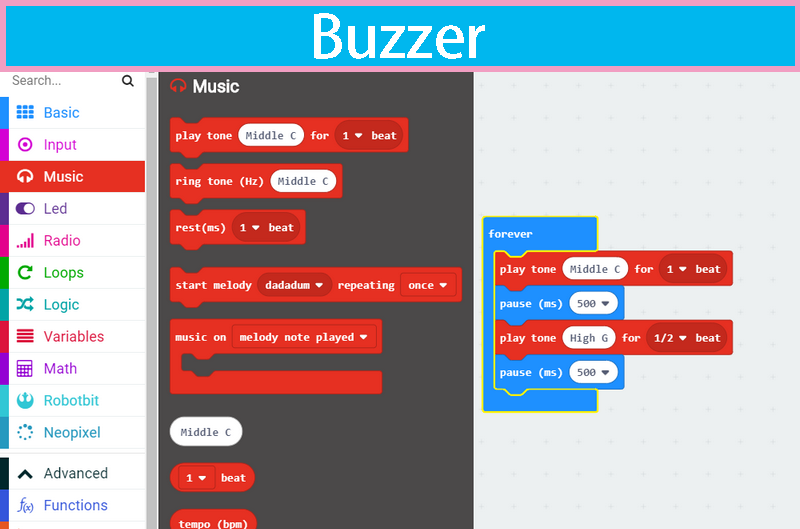
Blocks for a buzzer

The first block simply lets the buzzer tweet, the second block may output a melody. The melody notation definition locates at the micropython’s music tutorial page.
http://microbit-micropython.readthedocs.io/en/latest/music.html
We have port it to arduino, you can find the source code in the minilfr library under kittenblock’s install location.

Make a police siren
Let’s make something fun, here we use a variable and increasing loop to simulate siren of a police car.

You may find that the effect is a little cracky, no problem, translate it into arduino c++ and burn to the robot and check again. The offline code runs way more smooth than the online mode, this is because in online mode kittenblock send instructions line by line, it takes much time in the communication and instruction decoding.
Motor Control
The Motors

The motors of MiniLFR use N20 dc motor(3V) with metal gearbox, the reducer ratio is 1:30. If you need replacement, please tell the provider these parameters.
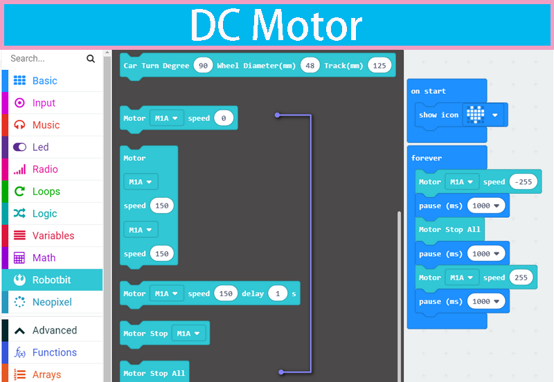
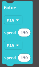
Blocks for motors

The speed value ranging from -255 to 255. Positive speed makes the motor roll forward, and vice versa. The second block with a delay control, the robot will stop after milliseconds passed.
Motor rolling
Here we demonstrate how to make the MiniLFR go forward and back then rotate in the ground.

If you find the USB connection not so convenient, please refer this post on how to use the wifi module, it is based on Kittenbot but works with MiniLFR.
http://learn.kittenbot.cc/en/latest/kittenbot/11WifiUploading.html
You may use wifi communication for online mode, and make minilfr a remote control car. Of cause, you can download it into the robot too.
Buttons

Block for buttons

The first block is a hat block type, which means this is a trigger source for following events.
The second block is a boolean, it will return true while the buttons are pressed. Be noticed that report/boolean block will only return value when it is executed, but hat type will be triggered once the condition met.
Loop reading
Let’s make use the buttons to control the spotlight. In the following code, we use while looping read first.

We add 0.5s delay for button debouncing and prevent retry to quickly.
Button as a trigger source
We can also use hat block here and makes the code more concise.
The hat block not only works in online mode, but you can also translate into arduino c++.
#include <Arduino.h>
#include "MiniLFRV2.h"
int my_variable;
MiniLFRV2 mini;
void _callback_BUTTON_1(){
mini.spotlightSet(1, 1);
}
void _callback_BUTTON_2(){
mini.spotlightSet(0, 0);
}
void setup(){
mini.init();
mini.registerCallback(BUTTON_1, &_callback_BUTTON_1);
mini.registerCallback(BUTTON_2, &_callback_BUTTON_2);
}
void loop(){
mini.loop();
}
The mini.loop function do all the event housework in the main loop, just like any operating system routine.

The Infra Sensors
There are five infra transceiver sensors mounted in the bottom of MiniLFR, as shown below.
These sensors are used to detect the black tap track below.

Block for infra sensors

Please see the first picture for the slot indexes.
There is only one block for the infra transceiver sensors in kittenblock, the other two infra related blocks are for the infra remote controller we will talk about it later.
Read the sensor
Put the MiniLFR on a black tap, click the sensor reading block to see what the sensors report relative to on or off the tape. And the value also varies by the distance to the tape, this is why you need to flatten the map.
The return value of the sensor reading block is already calibrated, which may eliminate the hardware difference between these sensors. You may calibrate the sensors again to see if the same.
Simple line follow algorithm
Here we make a very simple line follow by using the graphical blocks.

We make three separate functions:
- one to check the button’s state
- one to read the sensor’s values
- one to execute
Then merge these guys together in the main loop

You may need a wifi connection here to debug the code. Modify the threshold value in the look loop based on your actually reading.
Once the coding works in online mode, try to solidify the program to make it run more smoothly.
Infi RGB Ring
Hardware of RGB Ring

You may plug the RGB ring module directly to MiniLFR
Check the pic below to see how the pixels arranged.

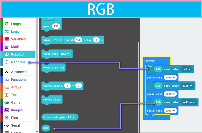
Block for the RGB Ring module

Notice that in kittenblock there are three different sets of RGB controlling blocks, but they all share the same bright setup.

Controlling the pixels
More pixels means more freedom, take a try of the code shown below. You can also download the code to the main chip.

The RGB ring is based on most commonly ws2812, you can also connect your own RGB stript to MiniLFR by doing some wiring.
Nekomimi RGB pixel
The Nekomimi Module
There is a very cute ultrasonic module shipped with the kit. We give it a cute name too, ‘NekoMimi’ which means cat’s ears.

In this part, we only show you how to control the RGB pixel on each ear.
Blocks description

You may change the color of each or all pixel by setting the color in the second slot.

Color by distance sensing
Here let’s create a small programme that reacts to the distance reported by the ultrasonic sensor.

Both pixels on the ears will turn red if you put your hand close in front the module.

Nekomimi Ultrasonic Sensing
Hardware

The two ultrasonic transceivers mount in the front of module PCB, one to transmit 40k Hz sonic waves and the other one will catch it. The amplifier and logic circuit will count the time of fly and report to the main controller, the MCU will calculate the distance the distance based on the speed of sound in air.

The distance blocks

You can get the distance by clicking or execute the block in your code. The return unit is centimeter.
A simple object avoidance programme
We have already used the distance block in the last chapter, we just add two more motor rolling blocks here and make it into an object avoidance programme. You may also upload this programme to the robot.


PS: the nekomimi module only uses one pin for distance sensing, the one marked with D on the PCB.
Ir Remote Control
The infra transceivers

- Infrared receiver may accept infrared coded data
- Infrared emission tube can emit infrared coded data
- Infrared remote control can transmit coded key data
You can also make multiple MiniLFRs talking to each other by their transceivers.
Ir transceiver blocks

There are three blocks designed for the IR communication.
The first one is a hat type block which triggered by IR controller commands. Note that this block output the decoded IR remote controller data, the raw data define can be found in the source code of MiniLFR libraries.
The next two block used to send and receive IR data in string or number format, the maximum transmit length is 8 characters.
Spotlight response to ir remote controller

These codes can be also translated to arduino c++ and download.
#include <Arduino.h>
#include "MiniLFRV2.h"
int my_variable;
MiniLFRV2 mini;
void _callback_IR_1(){
mini.spotlightSet(1, 0);
}
void _callback_IR_2(){
mini.spotlightSet(0, 1);
}
void _callback_IR_POWER(){
mini.spotlightSet(0, 0);
}
void setup(){
mini.init();
mini.registerCallback(IR_1, &_callback_IR_1);
mini.registerCallback(IR_2, &_callback_IR_2);
mini.registerCallback(IR_POWER, &_callback_IR_POWER);
}
void loop(){
mini.loop();
}
Each IR key registered a callback function at setup procedure, and the mini.loop() handle all the rest.

The matrix display
The matrix display module

You plug this module onto MiniLFR directly, just as the two modules mounted on MiniLFR.
The block for the matrix display

There are 128 dots in the module, arranged in 16x8. It may display characters, numbers, symbols or icon.
We have created two blocks for matrix display module, one to manipulate the dots directly and the other to display string or number, and more blocks are on the go.
Animation Loop

In the following programme, we scroll some number and string first. Any string length less then four will not scroll and just show up if you want it to scroll try to add some spaces after.
The inner loop we display a simple animated frame by frame and finally clean everything up.

Introduction To Circuit Board
Here is the tutorials for MiniLFR Robot
Product Purpose
Robotbit designed for primary school students/training institutions/parents/ enthusiasts as a robotic accessory.
Ship List
RobotbitV2.0 x1 3D printed protective case Optional accessory: silicone sleeve and 18650 battery.
Product Instrduction
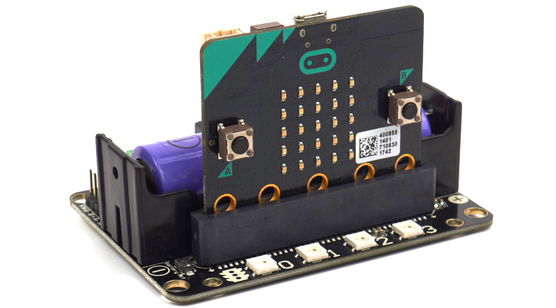
Robotbit is an excellent robotic expansion board specially designed for Microbit by KittenBot team. There is also a 3D printed protective case included.
Product Feature
It has a powerful ability to drive DC motors, stepper motors, servos, and onboard buzzer and RGB pixels and release all valid IO from microbit, with support the most common electronics module in the market. It comes with 18650 battery holder, integrated lithium battery boost, charging and protection chip. Support for external power input. Mechnically support for KittenBot robotic chassis and LEGO technical slots. The powerful drive capability and built-in battery make DIY more convenient and free. We have received unanimous praise from the school teacher training institutions and individual enthusiasts. It is an excellent choice for your robotic projects based on Micro:bit!
Product Parameters
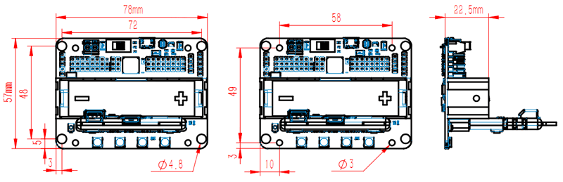
- Dimensions: 78mm x 57mm x 23mm
- PCB Thickness: 1.5mm
- Small mechnical hole: 3.0mm
- Big mechnical hole: 4.8mm
- Net weight (without packaging): 37.5g
Functional parameters
- 18650 battery voltage: 3.7V
- USB input voltage: 5V
- VM pin max ouput: 1A (with onboard battery)
- External Voltage Input (the green termial): 5V (only supports 5V input, do not connect over 5V, maximum current supports 3A)
Supported software
Available Coding platform: Kittenblock(based on Scratch3.0) or Makecode and python(Mu editor in microbit mode)
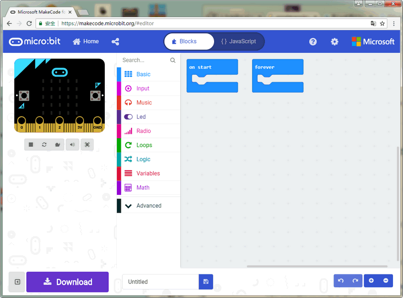
MakeCode from Microsoft
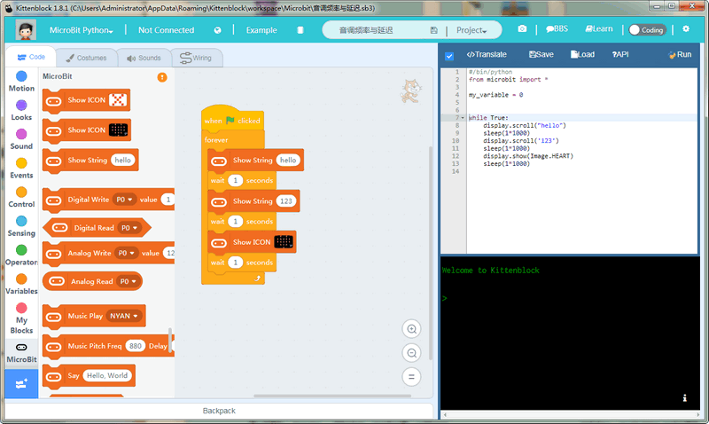
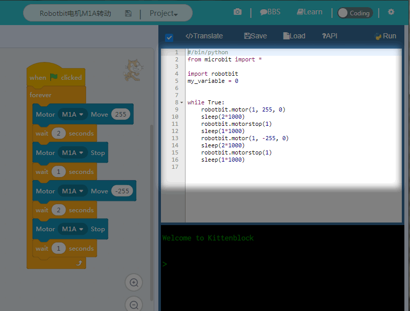
KittenBlock(Developed by Kittenbot Team based on Scratch 3.0)
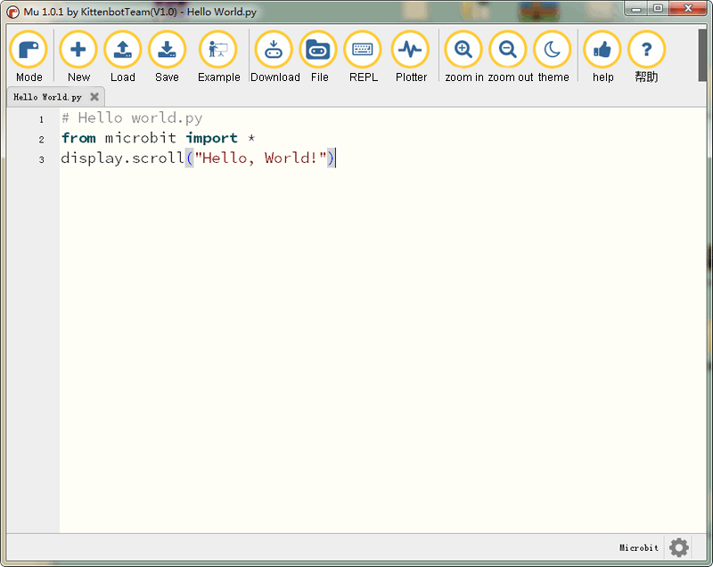
python
If you’re used to code programming and want to get started by microbit python you have two options, directly Mu Editoror kittenblock in micropython editor mode.
The above detailed tutorial can be found from our learn website for self-learning. If you encounter problems during the learning process, you are welcome to get us at our bbs or slack channel.
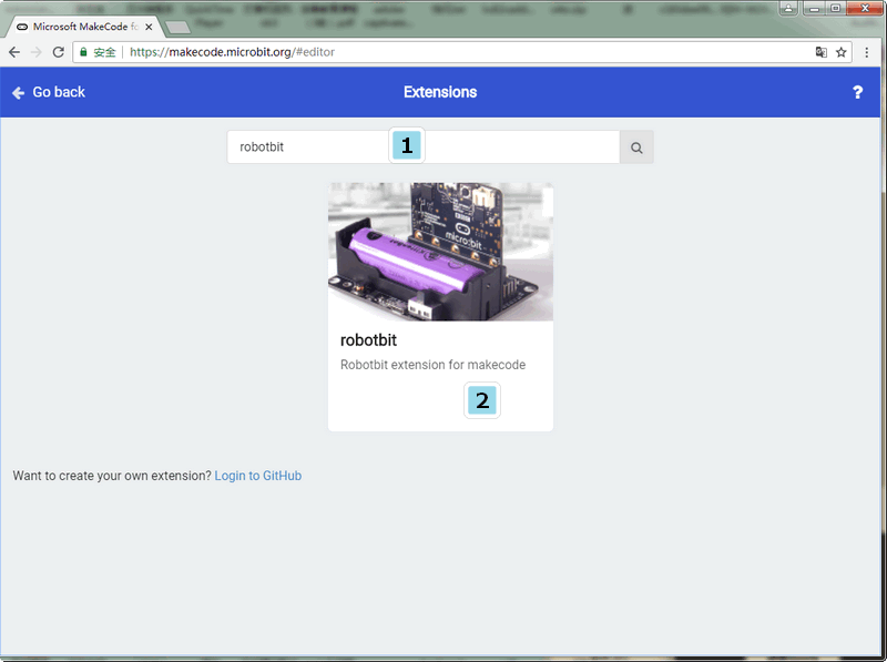
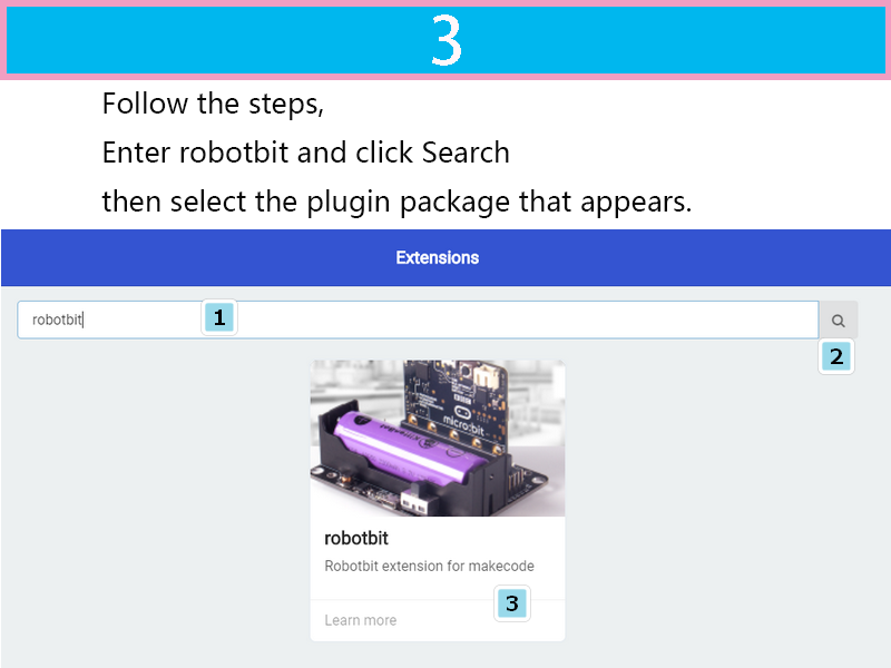
Makecode Extension
In makecode add extension panel directly search Robotbit. In our offline version of makecode, you may find Robotbit in the default list and other useful extensions.
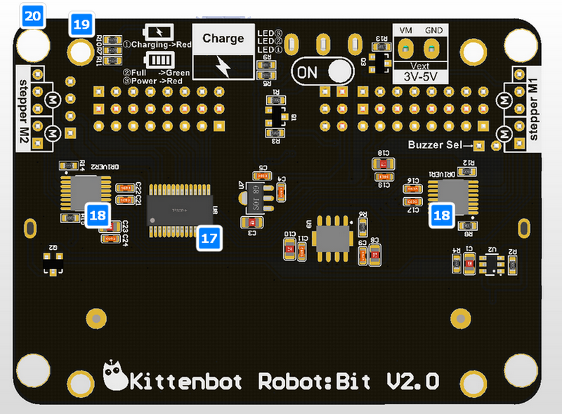
Hardware interface
- 5V external power input(with anti-reverse protection)
- Power switch
- Power Indicator
- Battery Indicator
- Micro USB charing port
- 4-channel DC motor / 2-channel stepper motor
- Jumper for buzzer selection
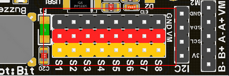
- 8 channel IO(corresponding to Micro:bit P0-P2、P8、P12-P15)
- 5V and GND port
- Buzzer
- 8 channel servo port
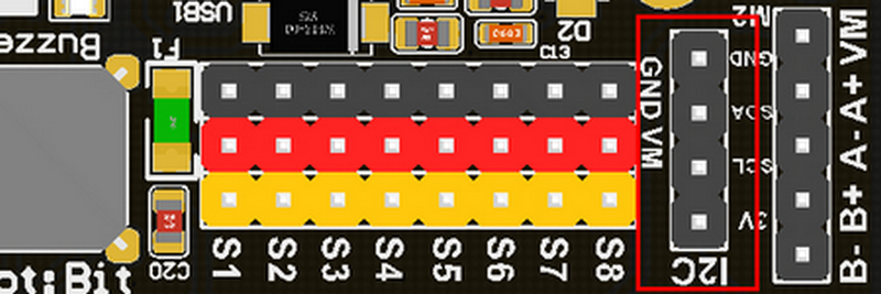
- I2C interface (expandable I2C module)
- 18650 battery case
- Bettery protection recovery push button
- Micro:bit edge connector
- 4x RGB pixel
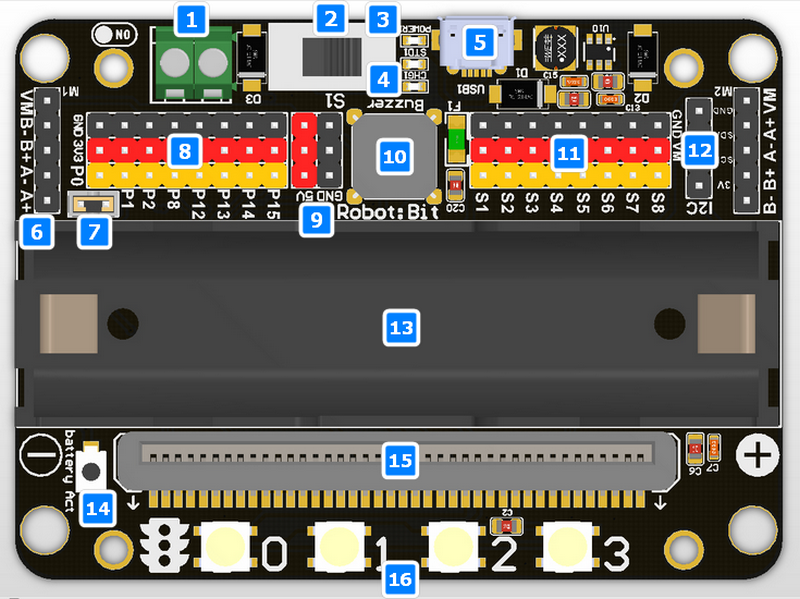
- Servo driver (PCA9685)
- 2xDc/Stepper driver (DRV8833)
- KittenBot robot chassis mounting hole
- Standard LEGO hole
Robotbit Detailed description
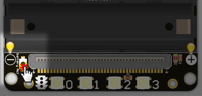
18650 battery case
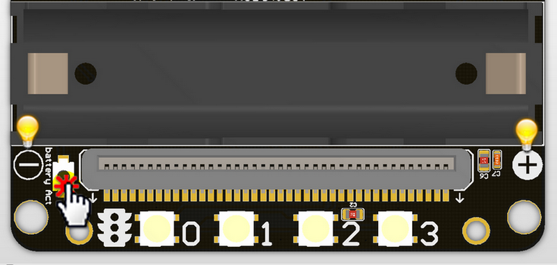 Once you got your RobotBit extension board please first install a 18650 battery, pay attention to the positive and negative pole (even we have anti-reverse protection). You have to activate the power management system by pressing the Battery Act push button. Each time you switch a battery cell or let the power management go into protection mode (over current or over discharge), you have to redo this step.
18650 Power switch
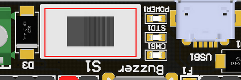
Turn on the switch (in the direction of green terminal input), will provide onboard 3.3V 5V and VM(motors and servos directly driver by battery cell)
Micro USB charger port
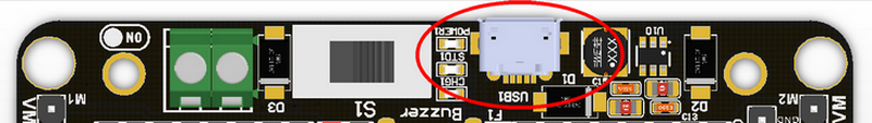
Only for charging and not for download! Computer USB host port or any other mobile phone charger which may output 1A or larger should be fine and may take about 2.5 hours to fully charge a 18650 cell. it will automatically cut off once full, no need to worry about overshoot.
Power and battery indicator
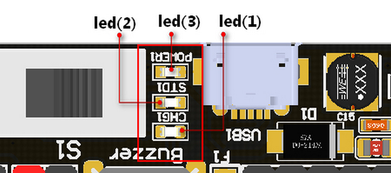
Led(3) is the power indicator, will be always on after switch is turned on. Led(1) is charging indicator, will be on while charing and Led(2) be on once fully charged.
Micro:bit stand edge connector
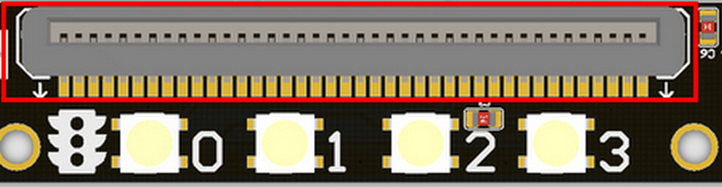
For installing Microbit mainboard. Please install Microbit with led matrix and RGB led in the same direction.
4x RGB neopixel
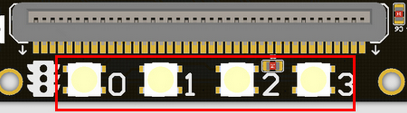
The robotbit extension for makecode has integrated neopixel support. Neopixel array connect to P16 of microbit.
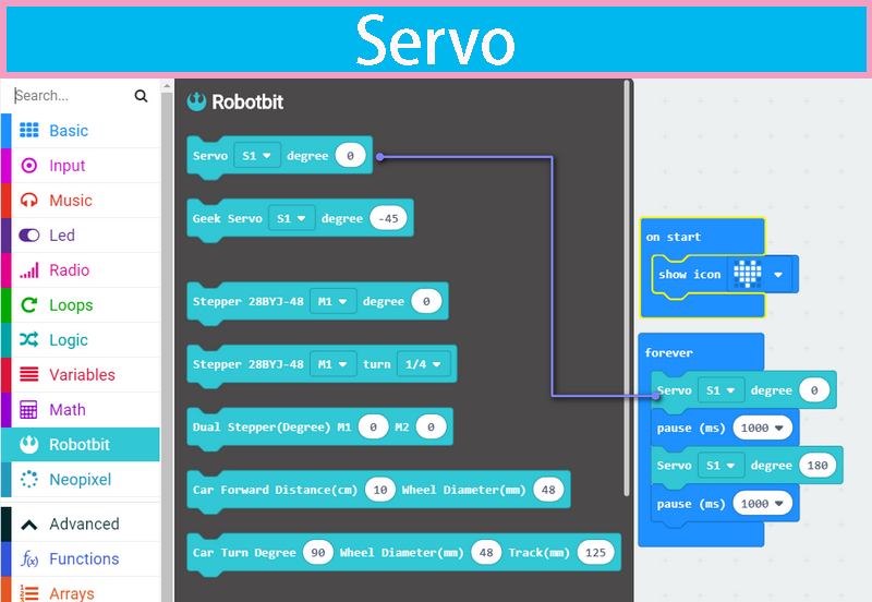
8 channel servo connector
Servos are driven by an extension chip (PCA9685) with the power source from battery or external input.The extension chip communicates with Microbit via the i2c interface, so these S1~S8 interfaces can only be used for pulse output not as common IO. With onboard 18650 battery cell, it may drive eight 9g hobby servo (with maximum current less than 2A). If you plan to use larger servos like MG995 please use an external power resource connect to the green slot (the input still 5V). Robotbit extension has built-in blocks for controlling servos.
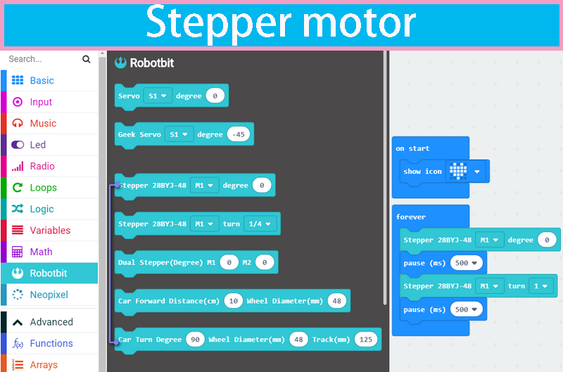
4 channel DC motors / 2 channel 28BYJ micro steppers
Robotbit extension has also built-in blocks for DC motors and steppers. With onboard cell you may drive 4x TT motors or 2x 28BYJ steppers, or a mixture of theese. Keep in mind that VM may out 2A to motors and servos. If you use external source please keep the input around 5V or less, a high voltage external input may damage the 5V boost circuit.
Buzzer and the selection jumper
The buzzer jumper cap is plugged in by default, and the corresponding buzzer is connected to the Micro:bit P0 port. If you need P0 for other purposes please unplug the jumper. The buzzer associate to music blocks in makecode.
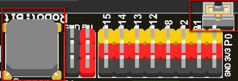
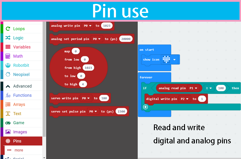
Micro:bit IO
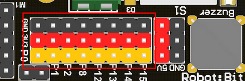
We have released P0-P2、P8、P12-P15 from Microbit to Robotbit for common IO usage. P0~P2 has analog read/write support, others may act as digital IOs. You may connect commonly modules for Arduino to Robotbit, there is also 5V output in case your module only support 5V power input. Please note that Microbit IO signal level is 3.3V.
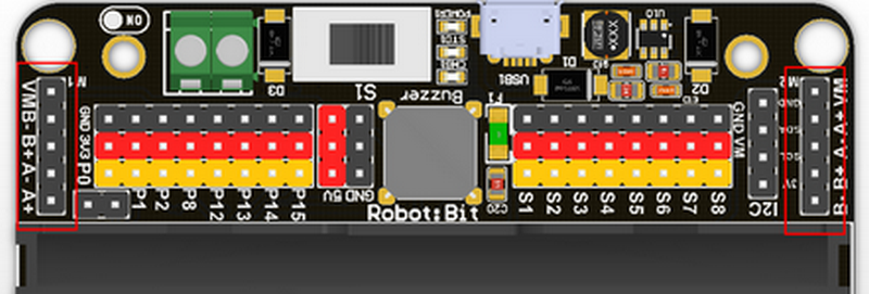
2PIN External Power Input
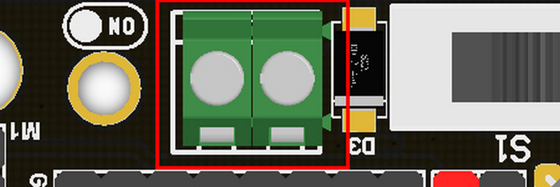
Although there is anti-reverse protection, but still pay attention while wiring. The positive and negative silkink of this interface is on the back of Robotbit. You can only input 5V or less into this port. If you have a higher voltage source you may need a LDO or DC-DC module to buck the voltage down.
Robotbit Quick start
Put the 18650 battery on the Robotbit, pay attention to the positive and negative pole.
Plug the Microbit into the Robotbit and pay attention to the plugging direction.
Click the battery activation button
Turn on the 18650 battery switch
Open the makecode editor (http://makecode.microbit.org) and press add package.
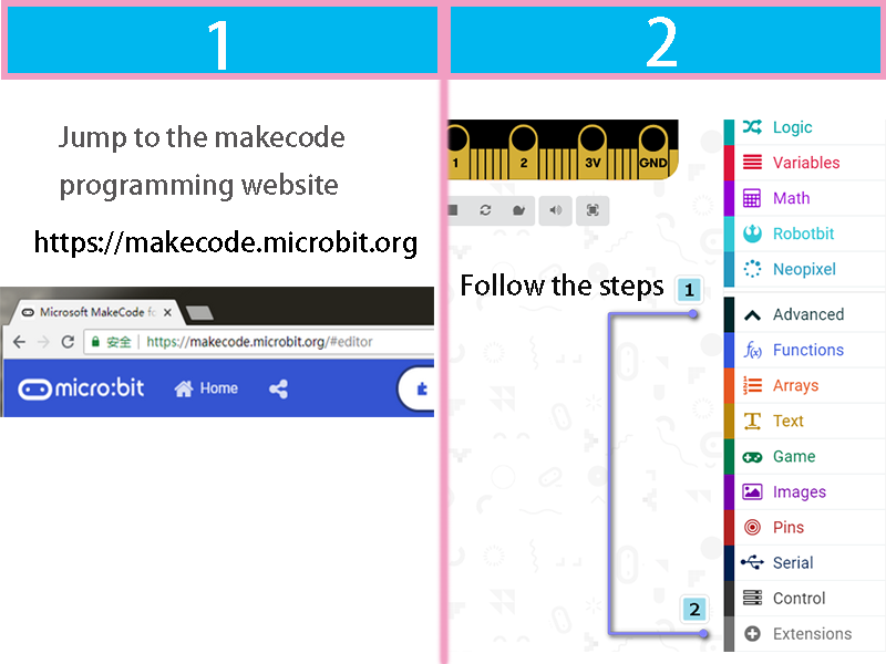
Search robotbit
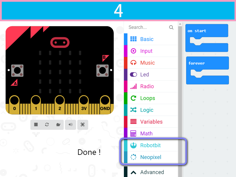
Drag some of the robotbit blocks out to workspace, remember to connect the corresponding motor servos, etc.
Before downloading, remember to connect to Microbit’s with a micro usb cable and click the download button.
After click download button, a file save box will prompt, please choose to save it to the Microbit removable disk.
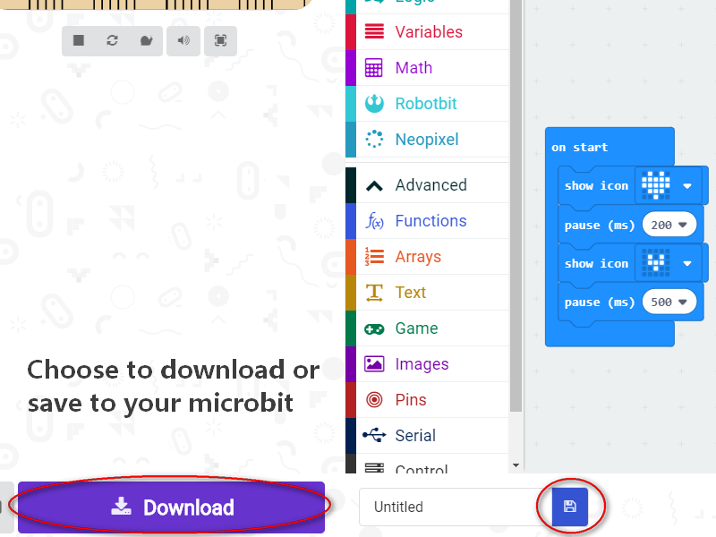
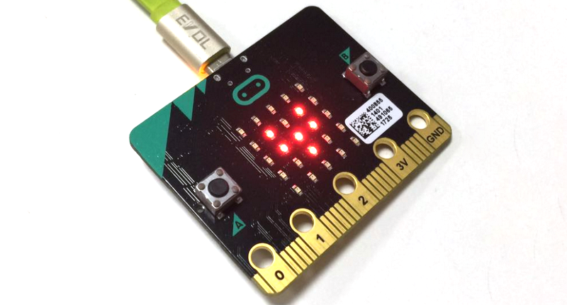
the final effect of the code block in the diagram above
F&Q
The battery is plugged in, there is no response after turn on switch?
Check if the battery activation button has been pressed? Check if the battery is positive or negative? Check if the battery has power?
What is the battery activation button used for?
In the case of overcurrent, or short circuit, or switch battery cell, the battery protection chip will protect the the circuit. Click the battery activation button to resume normal working mode.
Pluged in usb cable and I can’t find Microbit
The usb on the robotbit can only be used for charging. It can’t be used to download the program. It is plugged into the usb port of the robotbit. The computer will not respond.
Will it smoke if I insert battery inverse?
No, the robotbit design is anti-reverse protect in consideration of general miss operations. Inversely plug in will just not output power.
Will Microbit damage if plug in face back?
No, it will just refuse to work.
P0 pin control does not respond? Is it broken?
You need to unplug the buzzer selection jumper to use P0 as common IO.
Where is the rest of Microbit’s IOs?
Nearly 20 programmable IO ports on the Microbit, but many have been multiplexed with the dot matrix buttons on the board. Considering the inconvenience caused by multiplexing, beginners are likely to confuse on these. We have bridge 8 IO with no conflict to matrix or buttons to Robotbit, it should be enough for most diy projects. If you need all IO from microbit please choose IOBit from kittenbot team.
Can the servo interface act as common IO?
No, the servo s1-s8 is extended with a special servo drive chip and can only be used for servo drive.
What is the use of the VM on the motor interface?
The power source for 4-phase 5-wire stepper motor like 28BYJ. Usually, the VM is not used for the DC motor, and the DC motor only needs to connect A+A- or B+B-.
Can the board be placed on a metal surface or in a humid environment?
No, it will be short-circuited, pay attention to insulation
What is the voltage input for the green external power supply? What will happens with a higher voltage input?
Can only be connected to 5V, above 5V will damage the board, the current is recommended 2~3A, which means that the maximum current supported by the board is 3A
I did follow the tutorial, not results
If the test results are not corresponding, first check your wiring and procedures, some small place in general is missing, please double check.
The circuit board seems to be burnt out. How can I get warranty?
Microbit Robotic Kit
Here is the tutorials for MiniLFR Robot
Microbit line following and avoidance robot kit
Product Purpose
This kit is designed for makers or training institutions as a system of obstacle avoidance and others courses, and suitable for ordinary enthusiasts and makers to expand projects. We a complete graphical coding software support for this kit.
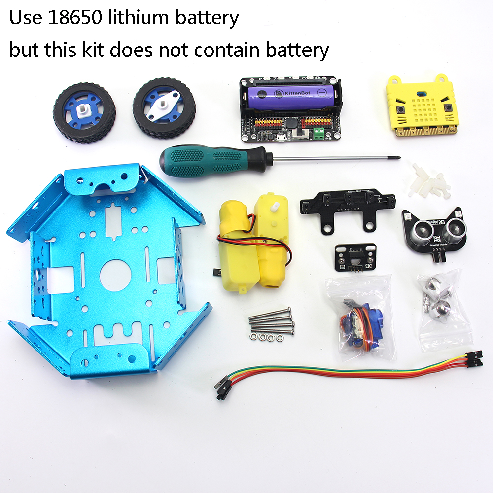
Product List
- Metal Chassis x1
- Microbit x1
- Robotbit x1
- TT Motor x2
- 9g servo parts package x1
- Five-channel line following module x1
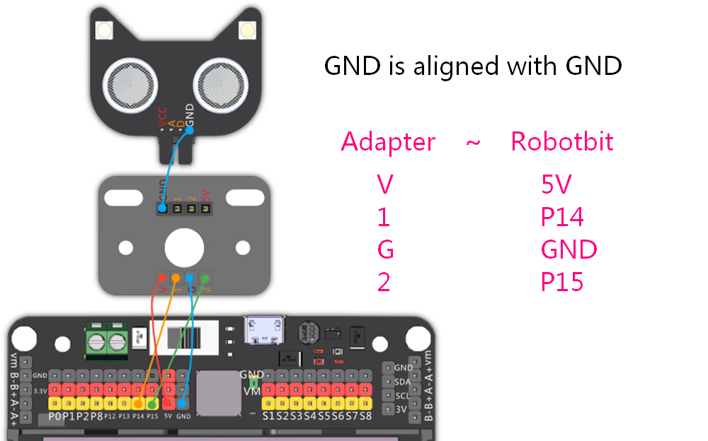
- Nekomimi ultrasound module x1
- Adapter plate x1
- Board support stub and screw x4
- M3 screw several
- M4 screw/nut x2
- Wheel caster x2
- Dupont wire several
- Screwdriver x1 (Does not contain battery)
Product introduction
This is a robotic product that combines obstacle avoidance and line following functions. For most people, they only hear or contact these applications through the electronic competition in college, but such assemble and programming process is complex and redundant, which basically sets a technology barrier for non-technique majors. Whether by choosing hardware component or writing code has sumped people who have an interest or idea on such projects. However, Micorbit combined with its expansion board Robotbit affiliate with graphical programming software support, there is no hard or hash work on fixing errors from library loading, nor the assembly of the kit, which greatly reduces the technical barrier. This makes people without a master degree on tech can also quickly get started and play their own intelligent robots based on their interests.
Product Parameters
- Dimensions: 170mm x 145mm x 110mm
- Net weight (without packaging): 390g
Specification
- 18650 battery voltage: 3.7V
- Operating voltage:5V
- Output current:1A(Supported by onboard battery)
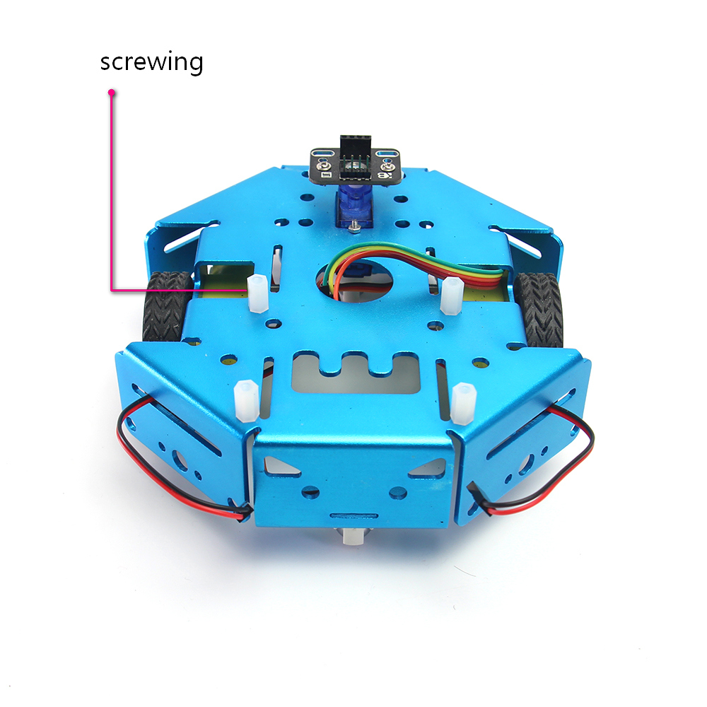
Assembly step
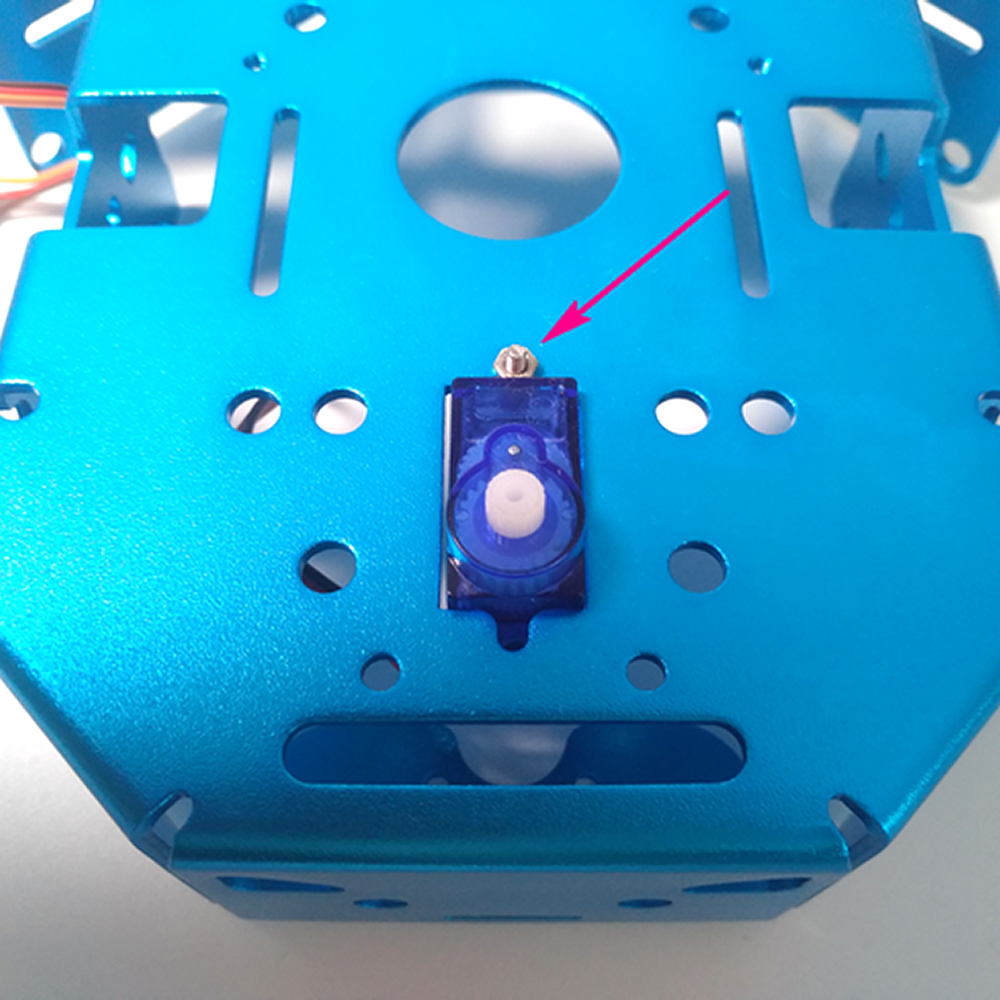
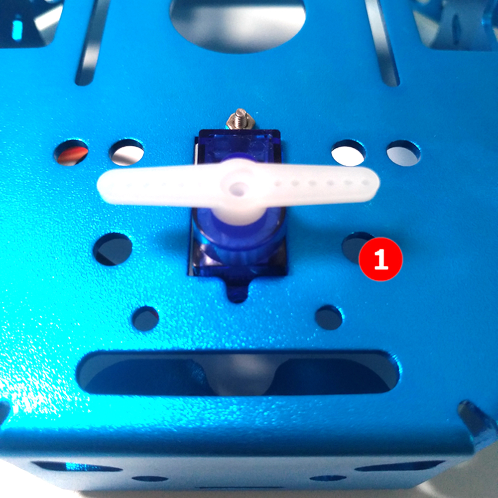
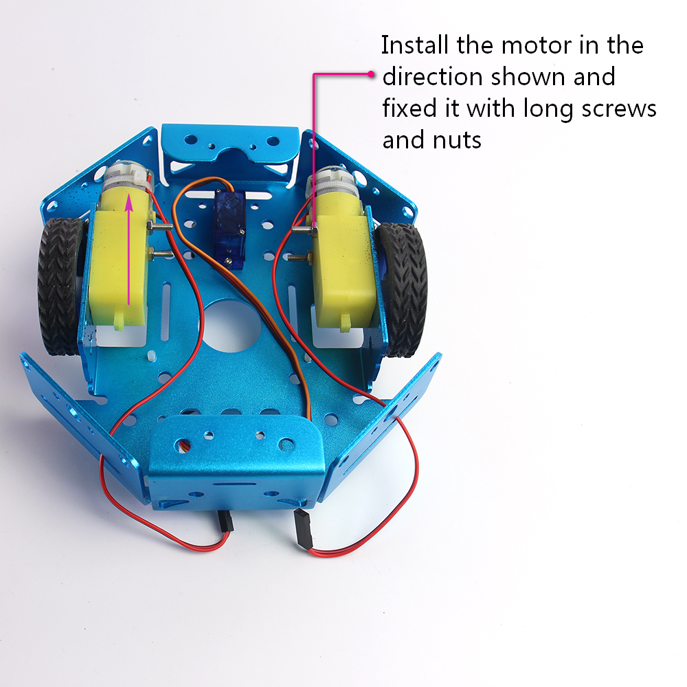
Insert 9g from the back to the chassis and secure it with the screws and nuts in the servo parts package.
Mount the bracket onto the servo rotor and check whether the left and right rotation limit angles. Basically, you should give same rotate freedom to both clockwise and anticlockwise.
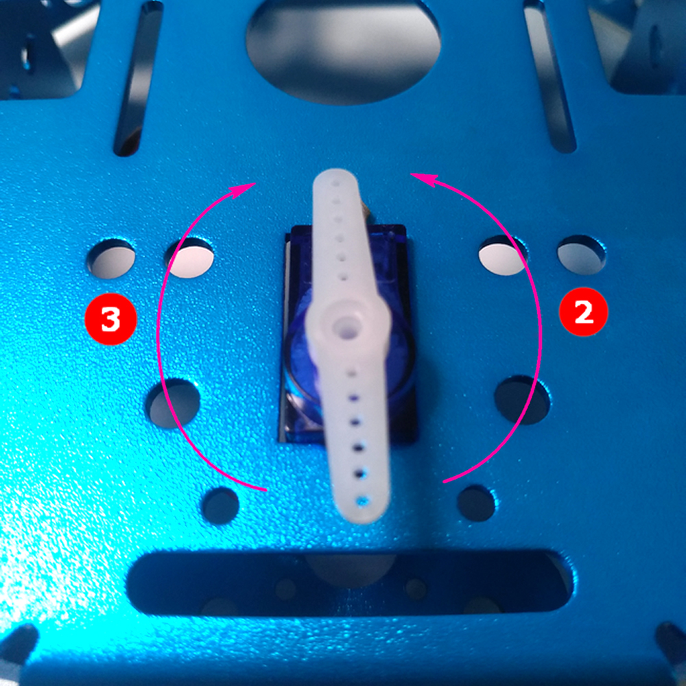
Let the servo geer keep in its middle position. Install the bracket to the adapter plate with screws.
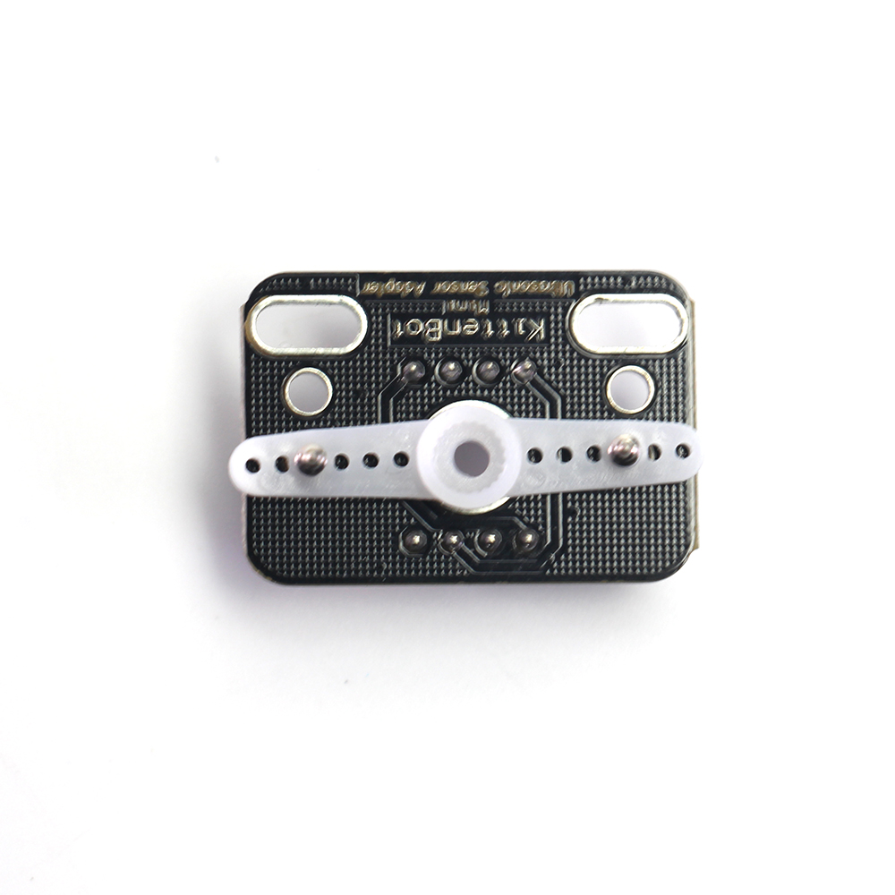
Insert the assembled parts on the servo rotor and tighten it with the small screws from the servo part package.
The TT motor screwed from the outside and the nut is fixed inside.
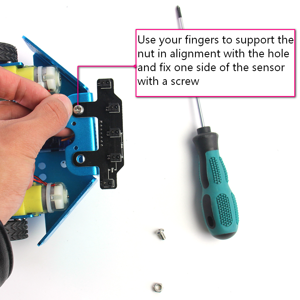
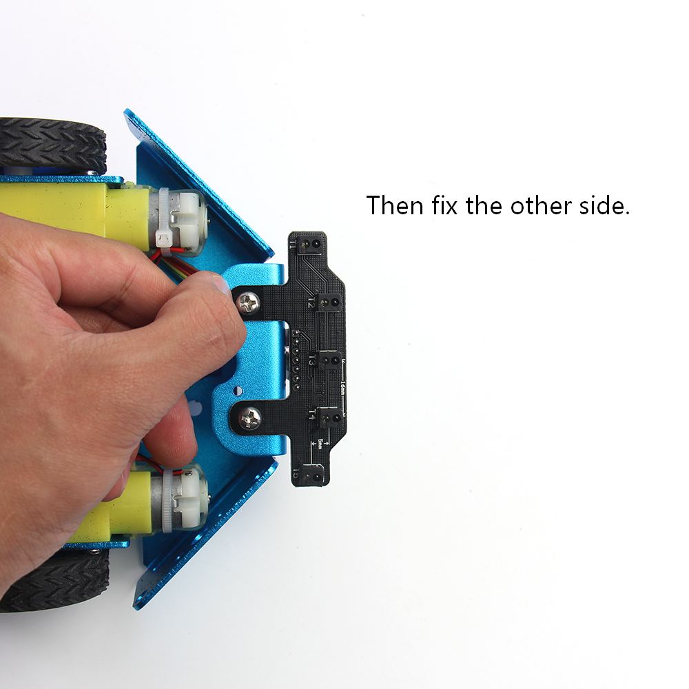
Tips on Installing the five-way line following module
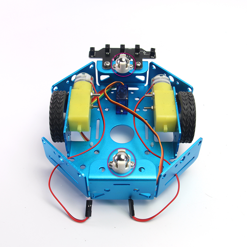
Two wheel caster installed on the front and back pallet.
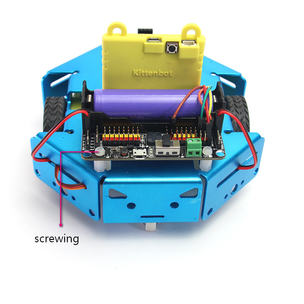
Plastic stub support for the robotbit. The mount hole is already threaded.
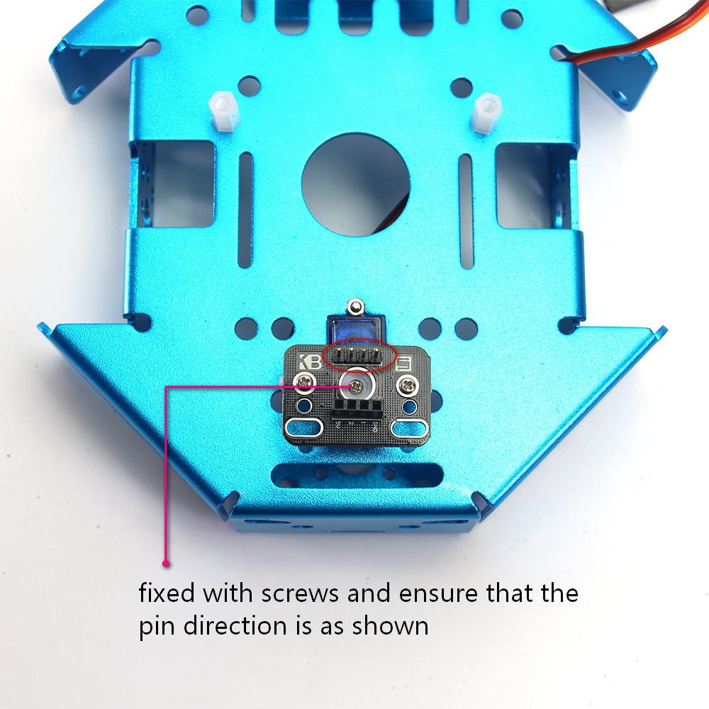
Wiring the ultrasonic sensor
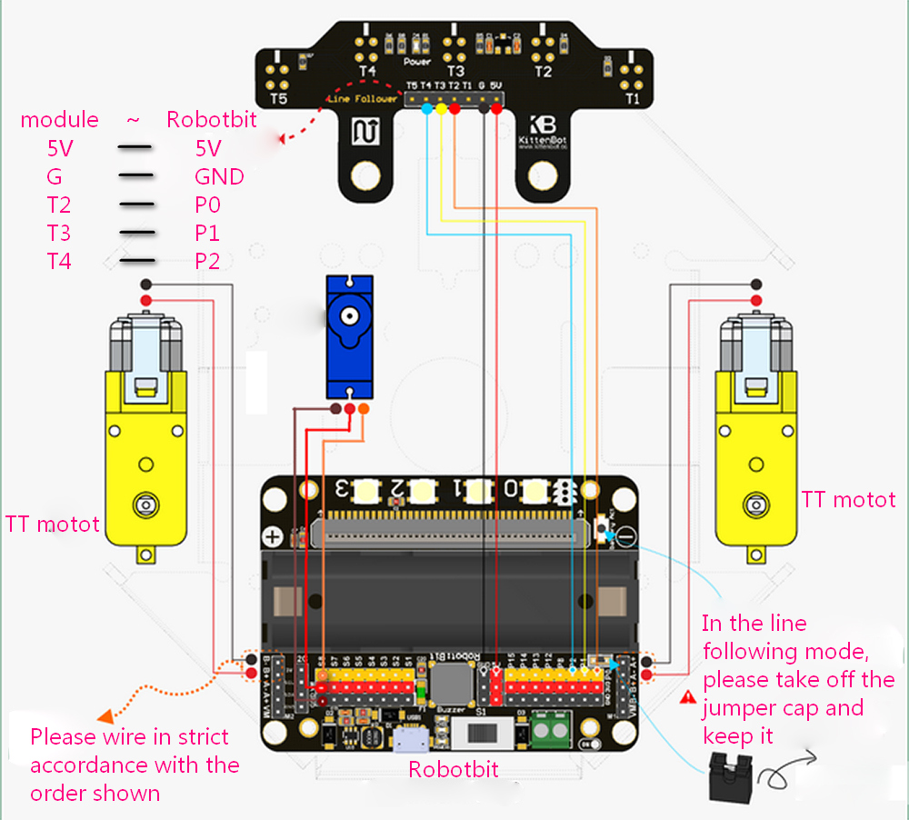
Wiring the five-channel line following sensor
Finished product display
Programming part
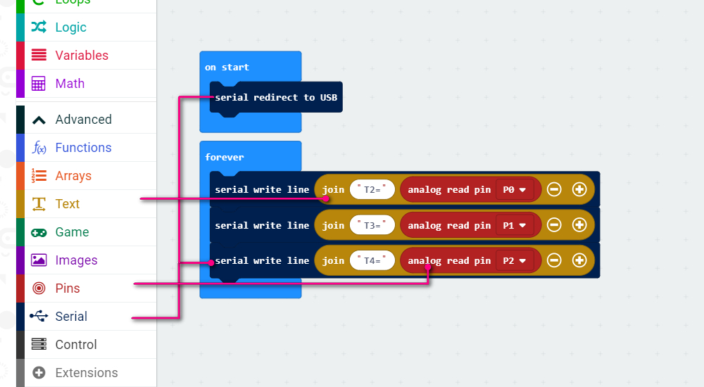
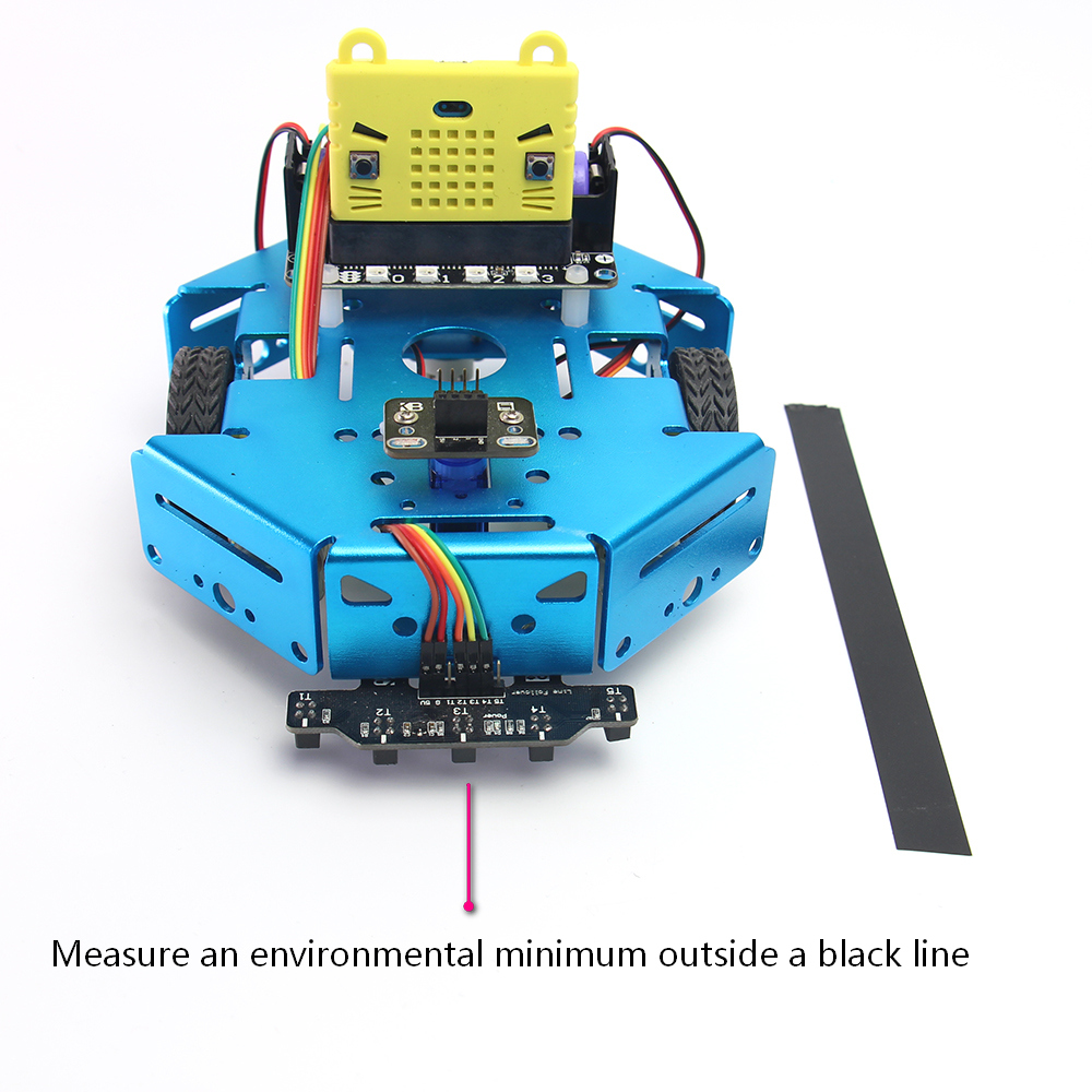
First we have to calibrate the infra sensor by reading the raw value of each sensor responding to black line.
First download the following serial port test program to micro:bit
https://makecode.microbit.org/_Cz94f2RrqTYf
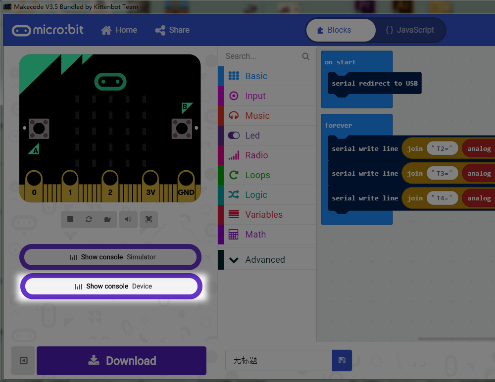
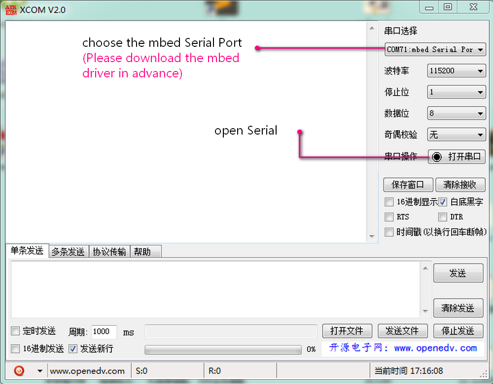
Then use the makecode or serial monitor tool to observe the output. The makecode offline version has inherit device console monitor, or you can use any serial monitor tool handy to you (even a arduino IDE).
 First, measure the normal value when out of black tape.
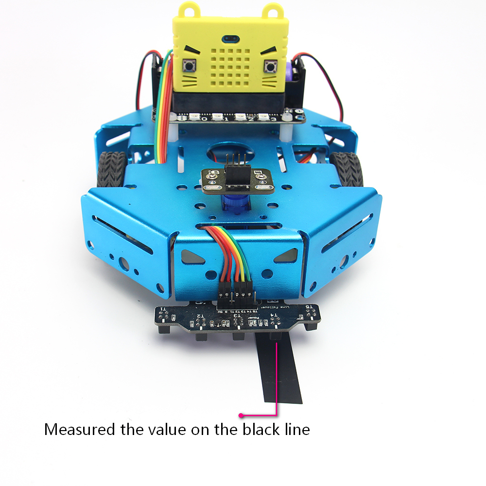
Second, measure the value when sensor over a black tape. Mark down all these online or outline value for each sensor, we need them in the next steps.
Three-channel line following
- working principle
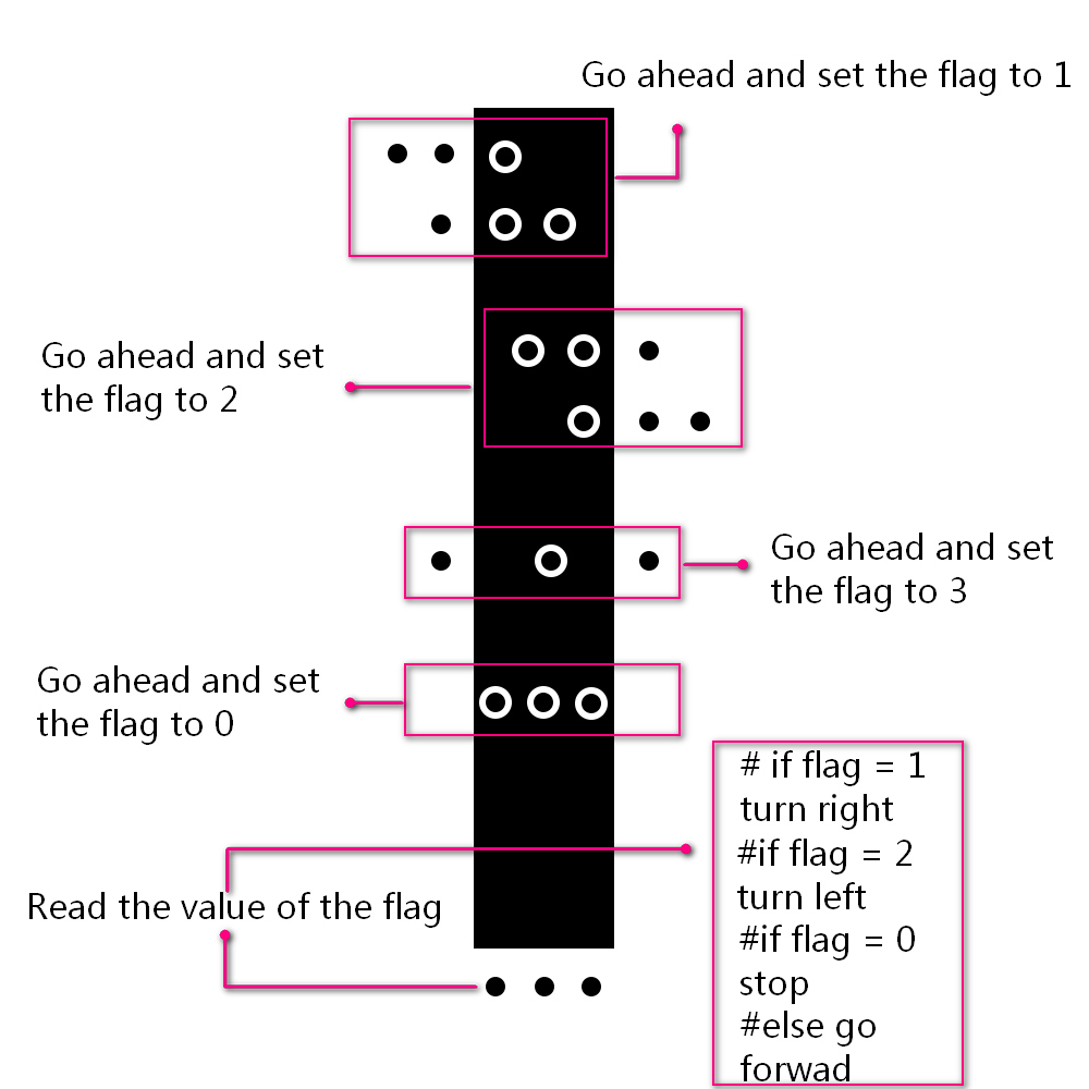
- program
https://makecode.microbit.org/_byh2fWUrF3u2
Ultrasonic obstacle avoidance
- working principle
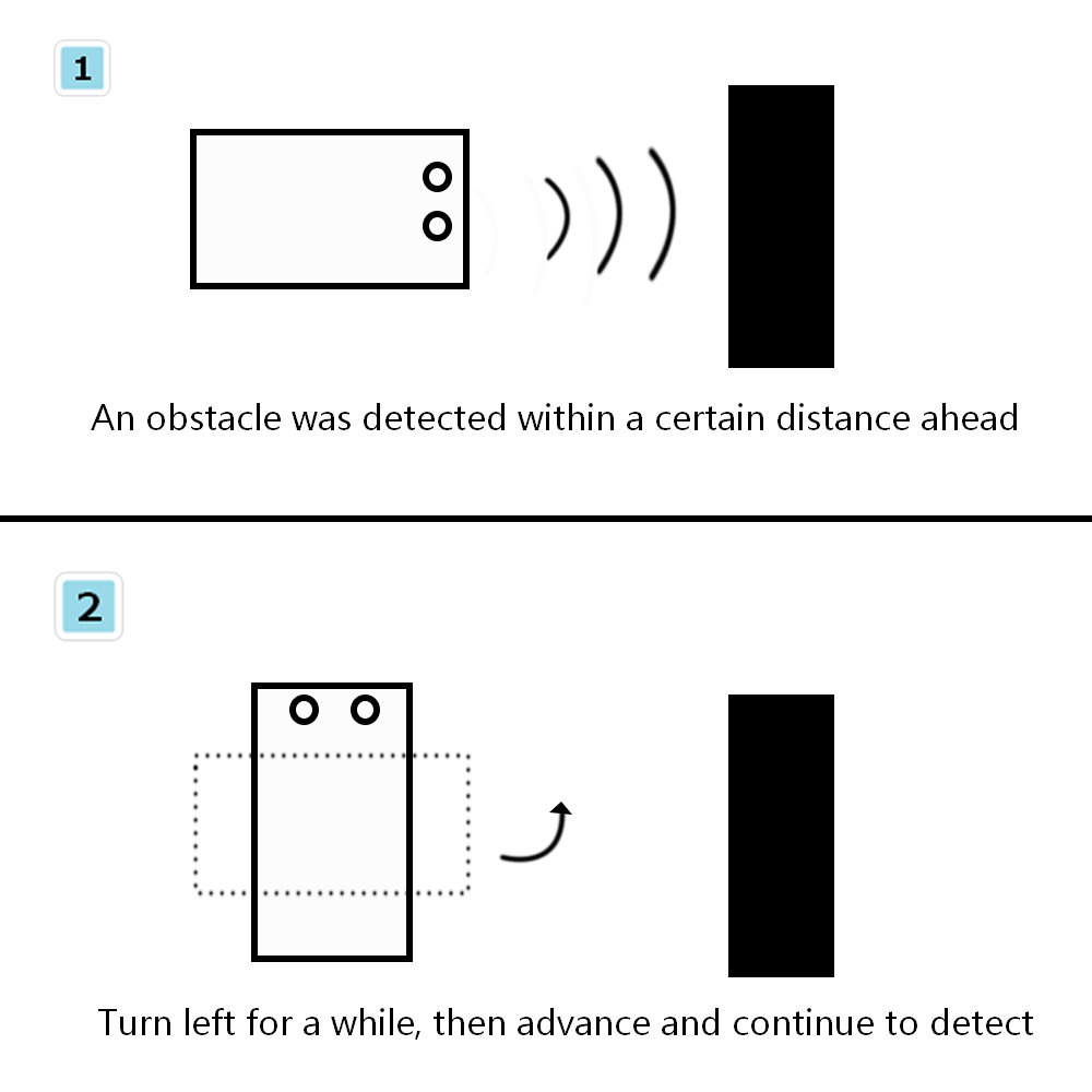
- program
Attentions
- Each time you plug in the battery and turn on the switch. The first thing you need to do is to activate the power supply.
- Regarding the wiring rule of the TT motor, the red wire indicate the positive sign and the black wire the negative sign. In this way, the positive number in the program can control the motor to rotate clockwise.
If you found the motor rotate contrary to expectations, just inverse the wiring terminal.
- The P0 pin is required when using the line following function,since the P0 pin is multiplexed with the buzzer, it is necessary to take out the jumper cap and keep it in a safe place.
This product is only suitable for children over the age of 14 for independent use. Children aged 8-14 should be accompanied by parents or teachers. Please use the instructions according to the official information before use. Do not plug in the circuit casually. Do not connect a large current servo or a high current motor to avoid burning the circuit board. Be careful not to place the control board on a metal surface or on a conductive object to avoid a short circuit. Avoid using it in wet and watery places to avoid short circuits. Do not swallow any small objects on the circuit board or machinery. Keep them out of the reach of children.